Custom Search
|
|
  |
|
|
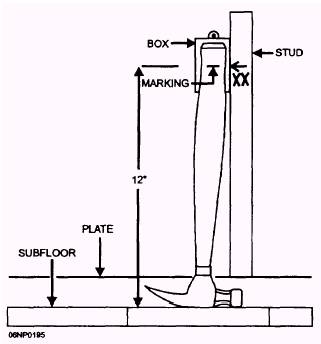
Box Mounting Height and Location There are no specific requirements for mounting boxes at a certain height. Mounting may be at any convenient height that meets the need for which the box is being installed. All boxes for the same purpose should be mounted at the same height. In some extreme cases, receptacle outlet boxes have been mounted in the wall parallel to the floor and just high enough to permit the cover plate to be installed. This type of installation requires that an allowance be made for the base finishing material as well as for the wall material when box depth is set. Receptacles set against the floor are hard to use and are hazardous in places where floors are mopped. Heights for receptacle outlets and switches are usually given in the plans. The measurement may be from either the subfloor or the finished floor and may be to the bottom of the box; the center of the box, which is probably the most common; or the top of the box. The most popular height for receptacle outlet boxes in the living areas of a house is 12 inches from the floor line to the center of the box. Many electricians mark their hammer handles to use as a guide for installing outlet
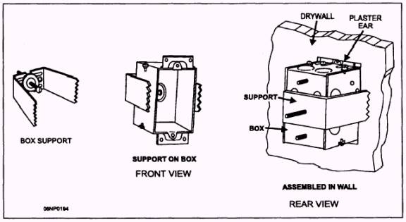
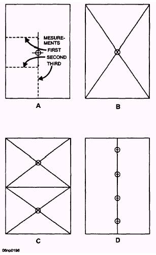
Figure 5-19.- Box support for hollow wall. boxes at the proper height, as shown in figure 5-20. Any number of other guides, such as a rule or a notched stick, can be used. It is a fairly common practice to mark the exact location of each wall-mounted box on the studs throughout the building before mounting begins. A lumber crayon, carpenter's pencil, or felt-tip pen that makes an easily seen mark should be used. An arrowhead, like that shown in figure 5-20, is used to show where the center of the box is to be placed. The arrowhead also points to the side of the stud where the box will be put. As an added convenience, symbols may be marked near the arrow to indicate the types of device to be installed. Some examples might be XX for a duplex outlet, SS for two single-pole switches, S3 for a three-way switch, or XR for a range outlet. Switch boxes and outlet boxes for laundry and utility rooms and garages are normally set 4 feet above the floor. This height is often increased 4 to 6 inches when some type of wainscoting or paneling 4 feet high is to be included as part of the wall. Boxes for outlets over counter tops are usually installed about 18 inches above the counter top (see NEC Article 210-52( c)( 5)). This measurement can vary a few inches up or down, depending on the height of the backsplash panel. Installing boxes without considering the splash panel could cause you to have boxes that overlap different wall surface levels. Ceiling boxes are located by a completely different method of measurement. Most rooms have at least one ceiling light located in the center of the room. A number of ways can be used to find the spot to mount this light box. One way is to use a rule or tape to find the halfway point across one dimension of the room and mark it, as shown in figure 5-21, view A. Make a second measurement across the same room dimension and mark the halfway point. Connect the two marks. Measure the other room dimension to find the center and mark it on the preceding line. This point is the place for the ceiling light box. Figure 5-21, view B, shows another way to spot the ceiling box. Run diagonals with string from opposite comers of the room. The point where the diagonals cross is the room center. Sometimes the position of the box is laid out on the subfloor. The point is then transferred to the ceiling by use of a plumb bob (a pointed weight on a string). When the plumb bob is suspended by a string held at the level of the ceiling joists with the point of the weight over the desired location, the top of the string will be at the spot where the box is to be mounted.
Figure 5-20.- Measuring box mounting height.
Figure 5-21.- Location of ceiling lights. Many rooms require multiple ceiling lights. If only two lights are involved, measure half the length of the room and then run diagonals for each half, as shown in figure 5-21, view C. This measurement procedure gives you the location for each light. A room that is to be lit with a row of lights will have them installed along the center line. The lights should be spaced so that the lighting is as uniform as possible. You can determine the spacing by dividing the length of the room by the number of lights. This figure is the space that is to be left between any two adjacent lights. The light at each end of the row is placed at half the preceding distance from the wall. This spacing is shown in figure 5-21, view D. If you take another look at view C, you will see that the space from the end walls to the lights is also half that of the space between the lights.
|
 |
|
|