Custom Search
|
|
  |
|
|
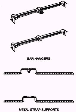
Box Mounting Between Framing At times, boxes must be mounted between the building or wall supports instead of directly on them. This positioning is particularly true of ceiling lights where the joists do not coincide with the spot at which the light is to be placed. In such cases, boxes must be mounted on a separate support attached to the structure. These supports may be purchased in the form of bar hangers or metal straps, or they may be constructed from metal straps or wooden strips. Figure 5-15 shows
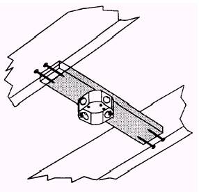
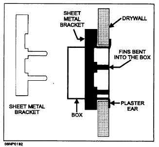
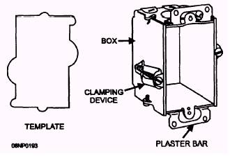
Figure 5-15.- Box supports. two typical bar hangers and two metal strap supports. You can see that one of the bar hangers includes a fixture stud that also serves to support the box when it is installed through the knockout in the box bottom. The other bar hanger supports the box by means of a clamp installed through the bottom knockout. Bar hangers with boxes already attached are available. Bar hangers come in different lengths with each having a range of adjustment to fit spaces of varying widths. Bar hangers are fastened in place by nails driven into the side of the joist or stud. Sheet metal screws or machine bolts and nuts are substituted for nails when metal framing is involved. Metal straps may have fixture studs or may have slotted mounting holes so the box may be attached with machine bolts and nuts. Strap supports come in different lengths with several nail holes in each end to fit various width spaces. Strap supports are nailed to the face of the joist or stud They have different offsets to fit different box depths or installation needs. Metal strap supports can be made similar to the manufactured one shown in the lower part of figure 5-15. Hole locations should be determined and holes drilled as needed for the specific installation being made. Wood supports can be made in a number of ways. About the simplest form is shown in figure 5-16. It consists of a piece of 1-by 4-inch lumber cut to length to fit between the joists and nailed in place. You need to allow for the depth of the box plus the thickness of the ceiling material when positioning the board for nailing. In some cases, two 1 by 4s may be nailed up with the wide dimension perpendicular to the joist or stud faces and the box mounted between them. Sometimes the ends of the 1-by 4-by 4-inch support is nailed to 1-by 4- by 4-inch blocks which, in turn, are nailed to the joists. Box Mounting in Existing Structures A completely different method of box mounting is required when a concealed extension is to be made to an existing circuit or when a new concealed circuit is to be added in an existing structure. The procedures discussed here pertain to mounting boxes in hollow walls; that is, walls, such as sheetrock or plaster on studs. Boxes must be equipped with plaster ears to assist in anchoring them in place. One method of hollow wall mounting is shown in figure 5-17. This method uses two sheet metal brackets to hold the box in place. The first step for this type of mounting is to locate and cut the mounting hole. After the hole is cut, hold the box in place in the hole with the plaster ears against the wall. Slip a bracket with the fins pointing out, long end first, between the box and the wall. Slide the bracket up until the short end clears the hole. Rush the short end into the hole and slide the bracket downward to center the fins with the box. Bend the fins tightly over the box edge and down against the inside. Repeat these steps for the second bracket. The box should now be held firmly in place. A second method of mounting a box in a hollow wall makes use of clamping devices attached to the box sides, as shown in figure 5-18. These boxes usually come with a stiff paper template to outline the hole that must be cut into the wall. If you do not have a template, put the box against the wall and draw around it. Be sure you do not include the plaster ears in your drawing. Cut the hole as indicated, Slip the box into the hole and tighten the clamping screws until the box is firmly anchored. One variation of this method works quite
Figure 5-16.- Woodbox support
Figure 5-17.- Bracket support of box in hollow wall.
Figure 5-18.- Box with hollow wall clamps. well with a lath and plaster wall. On the side of the box are cleats that unfold when the screws are tightened and clamp behind the lath. In this way, they support the ends that were cut when the hole was made. A third means of fastening a box in a hollow wall uses a support that is added to the box through the knockout in the back. The application of this support is shown in figure 5-19. After the knockout is removed, assemble the support to the box by inserting the bolt with the retaining washer through the knockout hole. Thread the bolt into the support Rush the box into the prepared hole and press on the bolt head until the ends of the support spring clear on the inside. lighten the bolt with a screwdriver until the box is held securely in place.
|
 |
|
|