| Tweet |

Custom Search
|
|
 
|
||
|
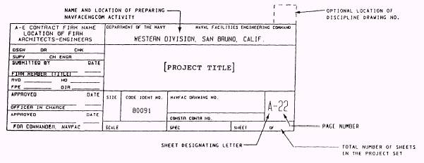
In the NCF, project drawings are normally divided into the following major categories: civil, architectural, structural, mechanical, and electrical. Regardless of the category, project drawings serve the following functions: . They provide a basis for estimating material, labor, and equipment before construction begins. . They provide precise instructions for construction, showing the sizes and locations of various parts. . They provide a means of coordination between the different ratings. l They complement the specifications; one source of information is incomplete without the other. Pages Most drawings have sheets/pages with designator letters (I-Index, C -Civil, A-Architectural, S-Structural, M-Mechanical, P-Plumbing, E-Electrical, and W-Waterfront). For example, as shown in figure 15-4, the sheet designating letter and page number is the 22d architectural page in a set of plans, so it is written A-22. The name, or title, of the project will be in the largest block on the page. For EO
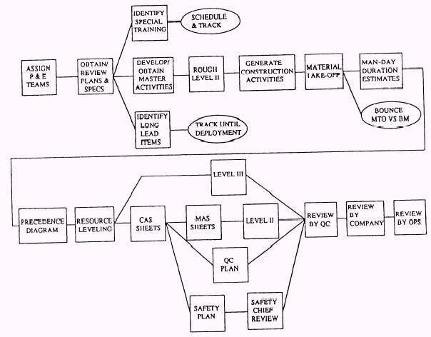
Figure 15-2.-Project planning flow chart.
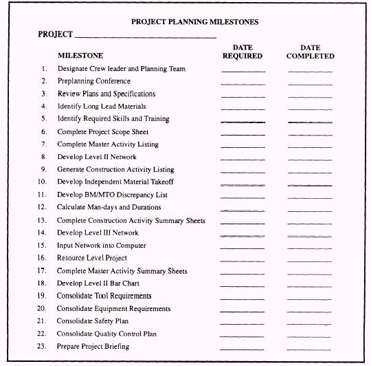
Figure 15-3.-Project planning milestones.
Figure 15-4.-Title block for drawings. work, you should concentrate on the index and civil pages. |
 |
|
|
||