| Tweet |

Custom Search
|
|
 
|
||
|
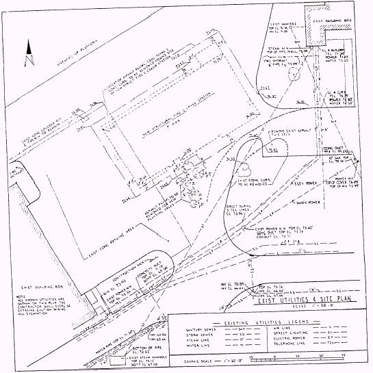
INDEX PAGE.- This page tells you where the project is located, what is in the set of drawings, and any special surveys that have been done. CIVIL PAGES. -Civil pages encompass a variety of plans and information to include the following: l Site preparation and site development l Fencing l Rigid and flexible pavements for roads and walkways . Environmental pollution control l Water supply units Depending on the size of the construction project, the number of sheets/pages in a set of civil drawings may vary from a bare minimum to several sheets/pages of related drawings. Normally, on an average-size project, the first sheet/page has a location map, soil boring log, legends, and sometimes site plans and small civil detail drawings. (Soil boring tests are conducted to determine the water table of the construction site and classify the existing soil.) A site plan (fig. 15-5) furnishes the essential data for laying out the proposed building lines. It shows the
Figure 15-5.-Example of a site plan with existing utilities. 15-5
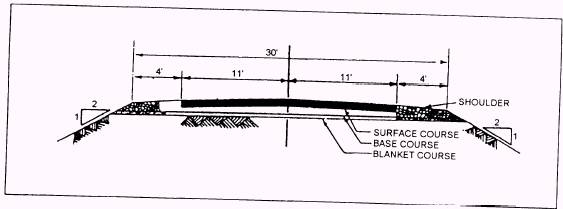
Figure 15-6.-Plan and profile sheet.
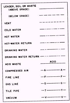
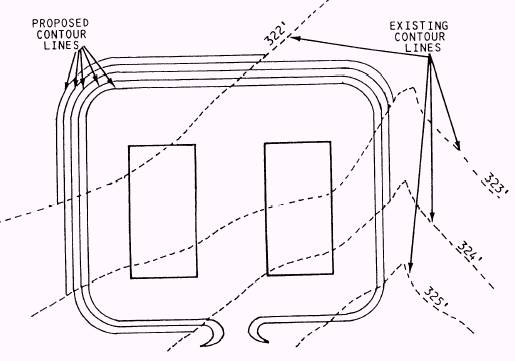
Figure 15-7.-Typical cross section. contours, boundaries, roads, utilities, trees, structures, References, and other significant physical features on or near the construction site. A plan and profile sheet (fig. 15-6) and a typical cross section (fig. 15-7) are other information found on a site plan. Symbols Symbols used in drawings are as follows: . A contour line shows us an imaginary line, representing a constant elevation on the earth's surface. Blueprints, or plans, use contour lines to show the final proposed elevations. . Existing contour lines identify the existing elevations (fig. 15-8). Existing and proposed elevations are used to figure cut-and-fill operations. . Proposed contour lines are those we work toward, You use them to visualize the finished product (fig. 15-8). .. Utility symbols identify utility lines. The symbols for pipe are shown in figure 15-9. Once all the
Figure 15-9.-Utility symbols for piping.
Figure 15-8.-Existing and proposed contour lines. 15-7 existing underground utilities are identified, use extreme care when working near them. Ripping up utility lines adds loss time to a project, adds to the cost of the project, and causes an inconvenience to people to whom the utilities were supporting. NOTE: Obtain a digging permit before performing any excavations on a project. Symbols for electric power distribution are shown in figure 15-10. Note the location of these lines not only for the reasons stated about pipe but also because of the risk of electric shock when a machine cuts an electric line. NOTE: On some occasions certain items are mistakenly left out on new drawings. Examples are buried telephone cables, electrical lines, waterlines, and fuel lines. Because of this, you must make it a practice to compare older drawings with new drawings and to your freehand sketches. Symbols for building material are shown in figure 15-11. These symbols are used in cross sections or cutaway views. They also label material as new or existing. |
 |
|
|
||