 |
||
|
|
||
|
Page Title:
SATS Field Installation Sequence |
||
| |||||||||||||||
|
|
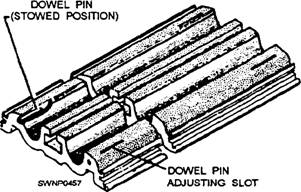
SATS Field Installation Sequence The sequence of laying matting for a runway where a guide rail for a catapult system is not required is not the same as for a runway where a guide rail is required. Figure 11-5 shows you what a guide rail looks like. When a catapult facility is used with a SATS installation, a guide rail is needed to provide stability to the dolly and the aircraft during the launch. The guide rail is supplied in 9- and 10-foot lengths and has connectors on both sides to mate with the mat end connectors. A U8-inch rubber seal is installed between each section to provide for thermal expansion and to prevent debris and soil from coming up between the rail sections. Dowel pins are used between two holes in the mats at each end of the guide rails to maintain alignment of the sections. The guide rail is installed concurrently with the mat field, and standard mat-locking bars are used to secure it to the mats. NOTE: The catapult and arresting system is not available currently in the ABFC System. However, it was originally designed for the ABFC System and could be used in the future; therefore, information on guide rails is provided.
Figure 11-5.-Guide rail.
Figure 11-6.-AM-2 mat installation sequence without a guide rail. The general sequence of laying matting for any length of installation where a guide rail is not required is to start at the transverse centerline and work toward each end simultaneously. The starter keylock section is laid, and then individual mats are laid in a brickwork type of pattern from left to right when facing the working area. The left-to-right sequence is dictated by the mat interlock design which is such that reversing the procedure is difficult and inefficient. The coated side is always "up," and the interlocking prongs on the 2-foot edge are always to the right and up. Survey lines are present to guide at least one edge of the section being laid to maintain proper longitudinal alignment. Other sections of the site maybe laid in the same reamer and at the same time if survey lines have been established, pallet staging has been accomplished, and sufficient personnel are available. A typical keylock section is laid every 100 feet, starting with the 100-foot mark on either side of the starter keylock. The general sequence of laying mating for the runway with the guide rail installed is to start at one end (at the approach apron) and work toward the opposite end. The guide rail divides the runway into two sections, 18 feet and 78 feet (or 18 feet and 30 feet for a 48-foot runway). Individual mats are laid in a brickwork type of pattern from the guide rail to the outer edge in each section when facing the working area. The starter keylock is not used when laying a runway with a guide rail. Instead, typical keylocks are laid at 100-foot intends on the runway, and other sections of the SATS field are laid as explained in the previous paragraph. Be sure to inspect visually upturned sides and end connectors of AM-2 matting for foreign matter before placing them in position. The presence of dirt, chips, stones, and so on, can prevent proper interlocking of the mats. Brooms or brushes can be used to clean foreign matter from the connectors. |
|
Privacy Statement - Press Release - Copyright Information. - Contact Us - Support Integrated Publishing |