 |
||
|
|
||
|
Page Title:
Mat-Laying Procedure without a Guide Rail |
||
| |||||||||||||||
|
|
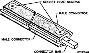
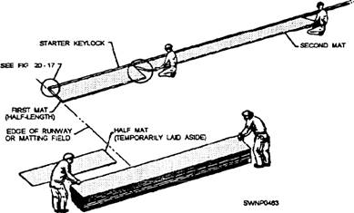
Mat-Laying Procedure without a Guide Rail The sequence for installing AM-2 mats and related components where a guide rail is not required is shown in figure 11-6. The sequence can be modified, so work proceeds on only one row of mats at any given time; however, SPEED OF INSTALLATION IS IMPORTANT. The sequence, as shown in figure 11-6, allows the use of at least two crews with six 2-man teams on each crew carrying and placing mats and keylocks. When placing AM-2 mats, you should have three types of keylocks: starter, typical, and female. You should use a step-by-step procedure to place the AM-2 mats. STARTER KEYLOCK.- The starter keylock is a narrow mat that is used to decrease runway installation time by approximately one half (fig. 11-7). Previous mat installation methods required assembling the runway at one extremity and working to the other end. The starter keylock is installed in the middle of the runway only and enables two mat-laying teams to start together and work simultaneously toward each end of a runway, section. Starter keylocks
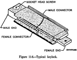
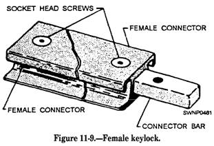
Figure 11-7.-Starter keylock. are furnished in 3-foot, 9-foot, and 12-foot lengths to allow for the staggering of joints in matting patterns. The starter keylock is coated with a nonskid material. It is not used in installations having a guide rail. TYPICAL KEYLOCK.- A typical keylock (fig. 11-8) is inserted every 100 feet in the pattern to permit the easy removal of sections of the matting for a multiple-mat replacement. For this reason, only a maximum of 50 feet of any one section needs to be removed to replace mats that could not economically be replaced as individual units by replacement mats. Typical keylocks are furnished in 3-foot, 9-foot, and 12-foot lengths to allow the staggering of joints of matting patterns. The typical keylock is coated with a nonskid material. FEMALE KEYLOCK.- A female keylock (fig. 11-9) is used to join two adjacent male mats. The female keylock is coated with a nonskid material.
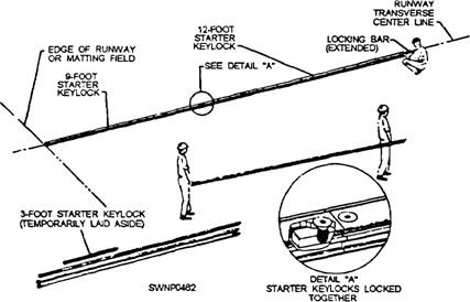
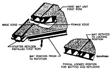
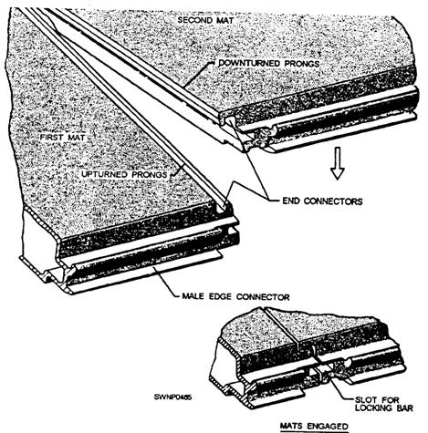
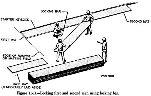
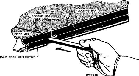
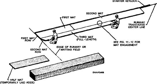
Steps for Laying AM-2 Mats and Keylocks The procedure for laying AM-2 mats and keylocks is shown in figures 11-10 through 11-18 and consists of the following steps: 1. Lay starter keylocks on the transverse center line of the runway. (See fig. 11-10.) A 9-foot starter keylock is laid at the outer edge of the runway. Remove the socket head screws from the keylock to allow for extending the locking bars into the next keylock section. 2. Place a 12-foot starter keylock next to, and aligned with, the 9-foot section. Move the 12-foot section against the 9-foot section, and adjust the locking bar so the socket head screws secure the locking bar in each section this procedure secures the 9-foot starter keylock and the 12-foot starter keylock, as shown in detail "A" of figure 11-10. 3. Repeat laying six more 12-foot sections and one 3-foot section of starter keylocks to complete the 96-foot width of the runway. NOTE: Initially, lay several transverse rows of AM-2 matting in one direction only from the starter keylock row. If matting is started on both sides of the starter keylock, a seesaw force could result, disturbing the alignment of the entire field. 4. With the nonskid side of the mat turned up and the upturned prongs on the right, align the first mat (half mat) on the left side with the starter keylock (fig. 11-11). Align the downturned prongs with the runway edge. Hook the female edge of the mat into the groove on the starter keylock (fig. 11-12) while holding the mat in an angular position. Rotate the mat downward to form the joint. (See fig. 11- 12.) 5. Lay the second and all successive mats the same way as the first mat (fig. 11-11) in relation to the starter keylock. The downturned prongs of the second mat should mate with the upturned prongs of the first mat, as shown in figure 11-13. When the mats are properly engaged, a rectangular slot is formed by the engagement of the end connectors. 6. Lock the first and second mats together, as shown in figure 11-14, by inserting the locking bar (fig. 11-15). NOTE: The first two mats and all mats in the first row should be aligned accurately before inserting the locking bar. Misalignment of mats will prevent proper installation of the second row. Locking bars may stick
Figure 11-10 -Placing starter keylocks on a transverse center line.
Figure 11-11.-Placing first and second mats
Figure 11-12.-Engaging first half mat (half length) to starter keylock. because of the natural waviness in the manufacture of the mat end connectors and the locking bars. A few light taps of a hammer should drive the bar into the proper position. 7. Place the third mat at the start of the second row, as shown in figure 11-16. Ensure that the third mat is aligned on the left side with the mat in the preceding row. Refer to figure 11-12 and step 4 for the engagement procedure, which is the same for the engagement of the third mat with the first and second mats. NOTE: The first row of mats and each alternate row thereafter is laid using half mats at the outer edges of the runway and full mats in between (fig. 11-6). The second row of mats and each alternate row thereafter is laid using full mats only. This method provides a staggered joint for greater matting strength. 8. Complete the first row, installing six more full-length mats and finally a half mat, using the same procedure as described for installation of the second mat. (See step 5.) NOTE: The first row of mats on the opposite side of the starter keylock row are all full mats (fig. 11-6). CAUTION Align the first row accurately with stakes or guidelines delineating the extent of matting. As work progresses, periodically check the alignment of mats already installed. Any misalignment causes a displacement of the runway from the planned position at the far end of the field. 9. Install the second and succeeding rows according to the procedure for the third mat (first mat in the second row) with one notable exception. The second mat in each row must first be hooked to the
Figure 11-13.-Engagement of the first and second mats.
Figure 11-15.-Insertion of the locking bar.
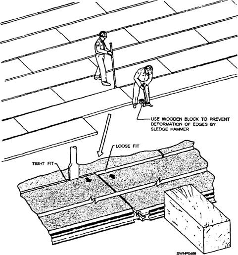
Figure 11-16.-Placing of third mat (full-length). preceding row while being held at an angle (fig. 11-12). The mat must then be aligned so when it is rotated downward, the end connectors mate properly, as shown in figure 11-13. NOTE: The mats are designed with an apparent `loose fit." This is to allow for expansion and also to allow for the natural waviness inherent in the extruded mat sections. Because of this, it is possible to have a row of mats "installed" but misaligned so as to prevent the proper engagement of one or more of the mats in the following row. (Such a condition in exaggerated form, and the method of corrections, is shown is figure 11-17.) Locking bars may be used as temporary spacers between the rows to prevent this. Place a locking bar on edge where the ends of two mats join and as the row ends. After three or four rows have been laid using locking spacers, proceed with the remainder of the runway or taxiway by removing the spacers from the furthest row and using them in the row just laid. CAUTION If it becomes necessary to adjust matting with a sledge, always place a wooden block
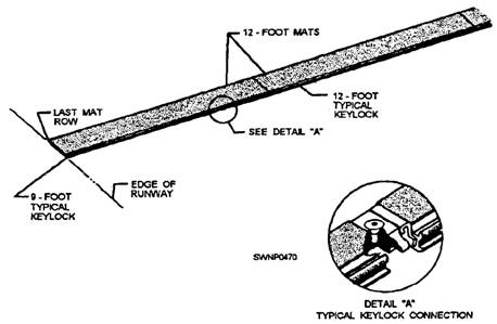
Figure 11-17.-Correction of mat misalignment. against the mat edge before striking, as shown in figure 11-17. 10. Every 100 feet, install a row of typical key-locks in the matting field (fig. 11-6). Place a 9-foot typical keylock at the outer edge of the runway with the female end of the keylock aligned with the first mat of the preceding row (fig. 11-1 8). Engage the female edge of the typical keylock with the male edge of the mat in the preceding row (similar to fig, 11-12 and step 4). 11. Place a 12-foot typical keylock next to the installed 9-foot typical keylock. Move the 12-foot section against the 9-foot section after first engaging the female edge of the keylock with the male edge of the first twoo mats in the preceding row. Raise the socket head screw in the male end of the 9-foot key-lock until the threaded hole in the female end of the 12-foot key-lock is aligned. Then secure the socket head screw in the 9-foot keylock, using the socket head screw wrench. See detail "A" of figure 11-18 that shows the typical key-locks secured together. Repeat laying of six more 12-foot sections and one 3-foot section of the typical keylocks to complete the 96-foot width of the runway. NOTE: After the laying of a row of typical keylocks every 100 feet, continue laying AM-2 matting, according to steps 4 through 9, to the ends of the runway. Runway APPROACH APRONS are required at each end of the main runway. These aprons are ramps made of mats placed to prevent the tail hook of a low
Figure 11-18.-Placing typical keylocks in a matting field. incoming aircraft from engaging or hooking onto the edge of the runway. (See fig. 11-19.) The aprons are constructed in a brickwork type of pattern but may be entirely of half-length mat units and extend across the full width of the runway. The free end of the apron should fall a distance of 18 to 24 inches below the normal ground level. The ground surface beneath each mat should be shaped to provide full contact across the bottom of the mat. After installation of the ramp, the excavation should be backfilled (ramp covered to the normal ground level). The backfill should be tamped and compacted. Installation of the ramp at the starting end of the runway can be readily accomplished although the installation procedure is slightly different. Place the side connector under the overhanging lip of the first row of mats and lift until contact is made. The mat is then rotated downward while keeping the two mats in contact. Locking bars are installed as described previously. MAT END RAMPS are used at the ends of the runways, laid on a hard surface (concrete), to smooth the passage from one surface to the other. The edge connection between the ramp and mat sections is the same as between two rows of matting. The ramp is fabricated from aluminum extrusions and is provided with welded inserts and extension plates, drilled and tapped to allow the ramp sections to be joined and anchored. (See fig. 11-20,) When installing mat end ramps, you should use the following procedure: 1. Install the first ramp at the right-hand corner, looking toward the opposite end of the runway. Place the next ramp adjacent to it, ensuring that holes in the overlapping plate on the ramp line up with threaded inserts on the matting ramp. Insert five flathead screws in each ramp, using the Allen wrench provided in the toolbox. Apply antiseize compound to the screw threads. 2. Next, use the locking baron the edge between the ramps and edges of the mats to assure the alignment is straight. 3. As the ramps are placed and screwed together, drill holes in the concrete for lag screw shields, using the holes in each ramp as a template. Drill holes to 5/8-inch diameter and 3 inches deep with the drill bit from the toolbox. Insert an expansion shield in each hole drilled in the concrete. Insert a lag bolt and washer in each counterbored hole. Tighten the lag bolts with the offset, square box-end wrench provided in the toolbox. 4. Complete the end ramp installation, as shown in figure 11-21. |
|
Privacy Statement - Press Release - Copyright Information. - Contact Us - Support Integrated Publishing |