 |
||
|
|
||
|
Page Title:
Mat-Laying Procedure with a Guide Rail |
||
| |||||||||||||||
|
|
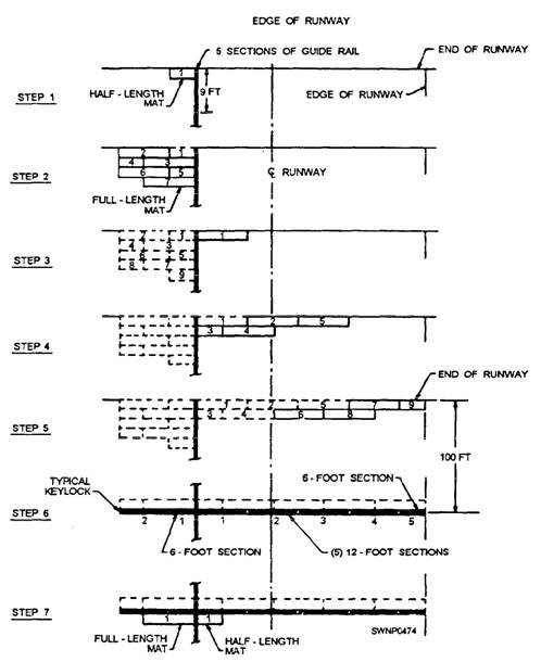
Mat-Laying Procedure with a Guide Rail The sequence for installing AM-2 mats and related components where a guide rail for a catapult system is required is shown in figure 11-22. The guide rail divides the runway into an 18-foot and a 78-foot
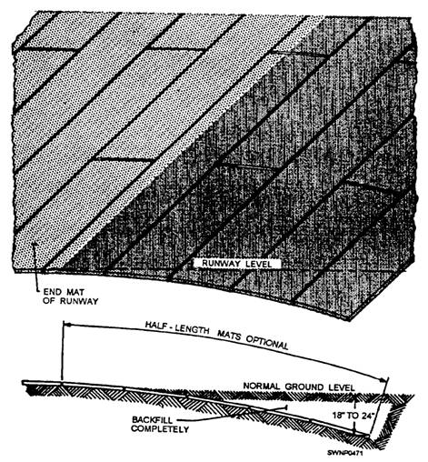
Figure 11-19.-Laying of runway approach apron
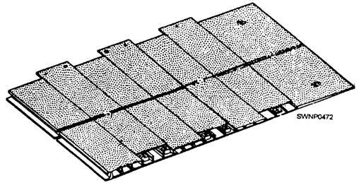
Figure 11-20.-Mat end ramp.
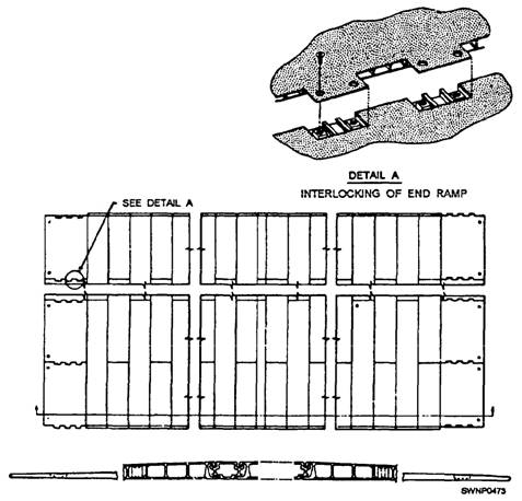
Figure 11-21.-Placememt of mat end ramps. section. The laying of matting should proceed in one direction only, from one end of the runway. Laying of the guide rail, mats, and related components is as follows: NOTE: The instructions presented here are for a 96-foot runway, but they are also applicable for a 48-foot runway. 1. Establish the guide rail center line, using a transit. 2. Install the first guide rail with dowel pins facing aft (opposite the direction of laying the guide rails). The first guide rail should be 9 feet in length, NAEC (Naval Air Engineering Center) Part No. 6125354, to prevent alignment of the guide rail joint with the mat joint. 3. Install the next four guide rails (10-foot rail) using spacer seals, NAEC Part No. 414233-1, and gap gauges, NAEC Part No. 414219-1, between the guide rail joints before driving the dowel pins. Check for proper position of the pins in the guide rails, using a pin gauge, NAEC Part No. 414212-1. NOTE: As the guide rails and mats are being laid, any visible depressions in the grade should be filled in and raked with the applicable hand tools. 4. Insert the transit target, NAEC Part No. 414691-1, in the center slot of the guide rail and preliminary alignment of each rail. 5. Lay the 18-foot section of AM-2 matting, as shown in figure 11-22. Insert the mat-locking bars between the guide rail and the mat. (See fig. 11-23.) 6. Insert the transit target, NAEC Part No. 414691-1, in the center slot of the guide rail and make the final alignment by shifting the five guide rails and attached mats. The guide rails and mats maybe shifted by pounding the edge of the guide rail or mat with a wooden block and a mallet. The guide rail center line should not vary more than 1/4 inch in 50 feet in the horizontal direction nor more than 1/8 inch in 12 feet in the vertical direction as determined by a 12-foot straightedge. The straightedge should be moved in 6-foot increments.
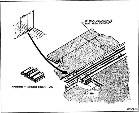
Figure 11-22.-AM-2 mat installation sequence (with guide rails-96-foot-wide runway). 7. Begin laying the 78-foot side of matting for the length of the guide rail and matting as aligned in step 6. Transverse mat joints should not vary more than 3 inches between the 18-foot and 78-foot-wide section of the runway where joints meet the guide rail and the mat. Installation of the 78-foot side may lag behind the guide rail and the 18-foot side but should never be installed beside the guide rails that have not yet been aligned according to step 6. 8. Install the next five guide rails. Guide rail joints should never be closer than 3 inches in reference to the transverse mat joints. (See fig. 11-23.) To ensure the 3-inch distance between the mat and guide rail joints, substitute a 9-foot length of guide rail for a 10-foot guide rail. Lay matting on the 18-foot side and then the 78-feet side. (See steps 5,6, and 7.) Continue installing the runway until 100 feet of the matting has been laid. NOTE: A minimum of ten gap gauges should remain installed to the rear of the guide rail dowel pins being installed. 9. Every 100 feet, install typical keylocks across the runway. Typical keylocks cannot be secured to the guide rail. Cut keylocks in 6-foot sections, as necessary, to ease installation on the 18-foot and the 78-foot sides of the guide rail. Refer to the section discussed previous] yin this chapter on "Mat-Laying Procedures
Figure 11-23.-Laying of guide rails and mats. without a Guide Rail," steps 10 and 11, for typical installation of keylocks in the field 10. Install approach aprons at both ends of the runway. Use 90-degree connectors to join the approach aprons to the field matting. (See fig. 11-24.) Connectors
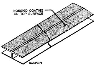
Figure 11-24.-90-degree connector. are 12-foot-long aluminum "H" sections that allow relative movement and slight misalignment between the adjoining sections of matting. |
|
Privacy Statement - Press Release - Copyright Information. - Contact Us - Support Integrated Publishing |