 |
||
|
|
||
| |||||||||||||||
|
|
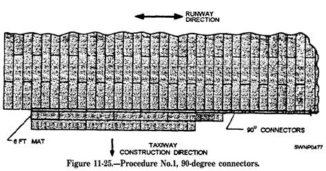
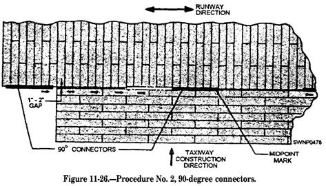
Field-Laying Procedure The sequence for laying an entire field is as follows: 1. The main runway 2. The lateral taxiways 3. The taxiway that is parallel to the runway 4. The parking stands and storage areas The above sequence may be modified in the interest of gaining time in the overall installation by laying the main runway and the parallel runway at the same time. Then the lateral taxiways and parking area can be installed. CAUTION If the latter procedure is to be used the distance between the runway and its parallel taxiway must be carefully controlled Since the mat width is 2 feet, a gap of almost 1 foot could occur at each end of the interconnecting lateral taxiway. The gap between the lateral taxi way and the long taxiway and runway should not exceed 2 inches. RUNWAY-TAXIWAY CONNECTIONS.Install W-degree connectors on the edge of the runway at the point where the lateral taxiways will connect with the runway. The 90-degree connectors may be used at other points where two mat-laying patterns, at 90 degrees to each other, are to be joined. NOTE: The 90-degree connectors can be used to connect the end of the lateral taxiway with the long taxiway also. The two procedures for installing 90-degree connectors are as follows: PROCEDURE NUMBER 1. Where the adjoining pattern has not been laid, install a sufficient number of 90-degree connectors along the 2-foot edge of matting, such as the edge of the runway, equal to the width of the taxi way or other section to be joined. Lay a half-length mat into the first 90-degree connector, so the end of the mat matches the end of the connector. Engage the prongs of a full-length mat into the prongs of the half-length mat previously laid and push into engagement with the 90-degree connector. Continue to lay mats in the above manner until the first row is completed to the length of the 90-degree connectors. Additional mats may then be laid in the usual manner. (See fig. 11-25.) PROCEDURE NUMBER 2. Where the adjoining mat pattern has already been laid, adjust the last few rows of matting (of the taxiway), so the space
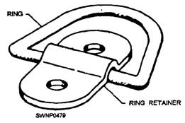
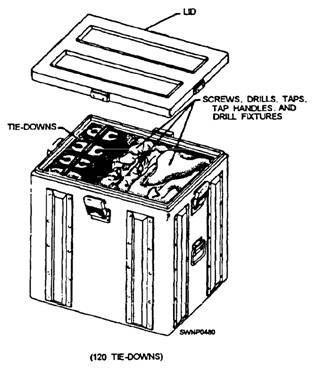
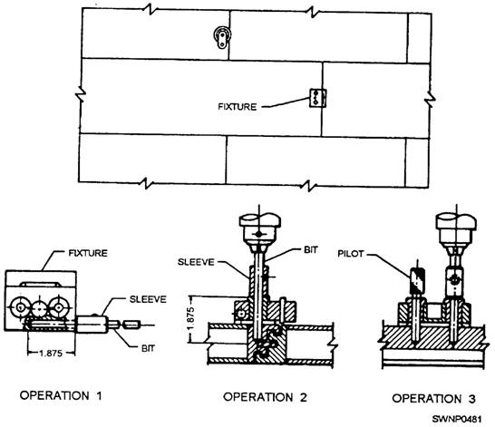
between the runway and the taxiway is between 1 and 2 inches. Place a 90-degree connector in position, as shown in figure 11-26. Using a sledge hammer and a wooden block, drive it into position. The most efficient method is to drive the 90-degree connectors from either edge toward the center of the taxiway. Place a mark at or near the midpoint of the 12-foot length of the mat. Drive the first connector to this mark. The positions of the remaining 90-degree connectors are then automatically established. Care must be maintained while driving the connectors not to allow debris to be scooped up by the forward edges of the connectors. INSTALLATION OF TIE-DOWNS.The-downs are provided for aircraft anchorage. (See fig. 11-27.) They are shipped in a package or container, as shown in figure 11-28. An individual container contains 120 tie-downs, plus the screws, drilling, and tapping equipment necessary to install the tie-downs. When tie-downs are to be installed, start by drilling and tapping the AM-2 matting on the prongs-down connector. Drill two holes for each tie-down ring retainer, using tools from the tie-down container. The procedure for drilling is as follows: 1. Secure the sleeve, 412131-1, to the 5/16-inch drill with the setscrew, using the drill fixture, 509044-1, as shown in operation 1, figure 11-29. Orient the sleeve to ensure seating of the setscrew on the body diameter of the drill. 2. Position the drill fixture, as shown in operation 2 (fig. 11-29), and drill one hole, as shown. Proper depth is obtained when the sleeve contacts the bushing. 3. Insert the pilot, 4121301, through the drill bushing into the drilled hole, and drill the second hole, as shown in operation 3 (fig. 11-29).
Figure 11-27.-Tiedowu
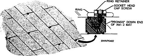
Figure 11-28.-Tie-down container. 4. Tap two holes 3/8 inch, 16 threads per inch, unified national coarse class 313 fit. Finish with the bottom tap to obtain 9/16-inch minimum full-thread length. 5. Store the sleeve and the pilot in the holes provided and secure with setscrews. After the drilling is completed, secure the ring retainer with two socket head screws. PARKING AND STORAGE AREAS.- The parking and storage areas should be installed next. Mats and locking bars are installed in the same manner as the runway and taxi ways, except that the staggered joint pattern is not mandatory. This means that the area can be built up in any random pattern and that all leftover half-length or full-length mats can be used. The 90-degree connectors should be installed between these parking and storage areas and taxiways according to the procedure outlined earlier. Install tie-downs on the matting in these areas, as shown in figure 11-30. BLAST DEFLECTOR INSTALLATION.- To shield the ground area around taxiways and parking areas from the blast effects from aircraft, install blast deflectors as required. Assemble blast deflector adapters to the boundaries of matting that will be
Figure 11-29.-Drilling jig for installing tiedowns
Figure 11-30.-Installing tie-downs in AM-2 matting. either male edges, female edges, prongs-down ends, or prongs-up ends. Three types of adapters are supplied to fit anyone of the joints. Erect AM-2 mats to the exposed upturned edge of the adapters to provide the blast shield. Use the adapters to support each AM-2 mat. (See fig. 11-31.) |
|
Privacy Statement - Press Release - Copyright Information. - Contact Us - Support Integrated Publishing |