 |
||
|
|
||
| |||||||||||||||
|
|
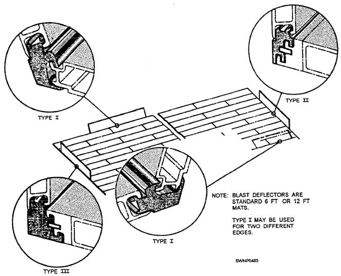
MATTING REPAIR During use in the field, matting may become damaged and require repair or overhaul. Some of the repairs that may be necessary are covered here. If you are called upon to make repairs other than those
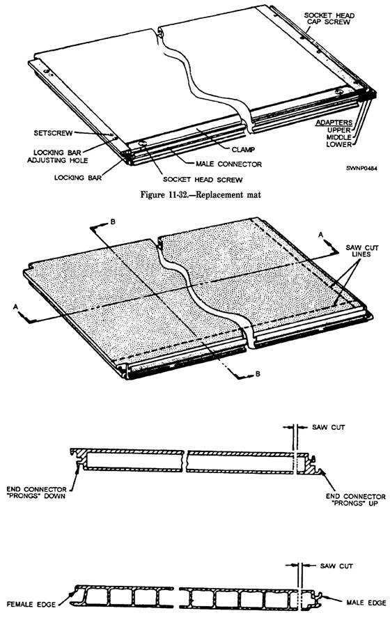
Figure 11-31.-Installation of blast deflector (adapters and mats). covered below, consult your leading petty officer for instructions. INDIVIDUAL MAT REPLACEMENT If an individual mat is damaged and cannot be satisfactorily repaired, damaged AM-2 mats may be cut out of the installation and replaced with a replacement mat assembly. A replacement mat is shown in figure 11-32. Replacement mats allow the replacement of damaged mats with a replacement item that duplicates the original installation. These mats are complete with a nonskid coating. Replacement mats are prepared from AM-2 mats by cutting off the prongs-up edge and the male connector edge and welding on adapters. Additional adapters must be bolted on at the time of installation. To replace a damaged mat with a replacement mat assembly, follow the procedure below. 1. Cut out the damaged mat so complete removal can be affected without damage to surrounding mats. this can best be accomplished using a portable circular saw, set for a 2-inch depth of cut. The cut should be made along the male edge and prongs-up connector. (See fig. 11-33.)
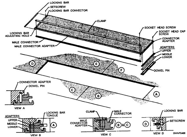
Figure 11-33.-Mat cutting for removing mat. 2. Ensure that all recesses in the mats surrounding the repair area are clean. Use a broom or brush to remove any debris. 3. Remove the male connector and adapters from the replacement mat, using socket head screw wrenches taped to the pallet. Be careful to retain the dowel pin in the lower adapter. (See view A of fig. 11-34.) 4. Place the lower adapter prong under the lower prong of the prongs-down end of the adjacent mat A, keeping the dowel pin up. (See view A of fig. 11-34.) 5. Place the middle and upper adapters on the lower adapter, using the dowel pin as a locating device. Ensure that the locking bar tongue on the middle adapter is in the locking bar slot of mat A and the upper adapter prong mates with the upper prong of the prongs-down end of the adjacent mat A. (See view B of fig. 11-34.) 6. Place the male connector into the female connector of adjacent mats B and C. (See view C of fig. 11-34.) 7. Place the female connector edge of the replacement mat over the grooves of the male connector edges of adjacent mats E and F (fig. 11-34) in the same manner that AM-2 mats are connected. Gently lower the replacement mat into place, being careful to lift the dowel pin into the hole in the connector adapter and the male connector adapter into the groove in the male connector. (See views A and C of fig. 11-34.) 8. Align the holes between the upper, middle, and lower adapters and the connector adapter. The dowel pin will provide at least approximate alignment, although some minor shifting of the replacement mat with a pry bar maybe necessary. Insert and tighten the four socket head cap screws with the 5/16-inch box wrench provided. (See view B of fig. 11-34.) 9. Place a clamp over the male connector. Alignment of holes can be accomplished by sliding the clamp in the adapter grooves. Insert and tighten the ten socket head screws with the 5/16-inch wrench. (See view C of fig. 11-34.)
Figure 11-34.-Replacement mat installation. 10. Using the 5/32-inch socket head screw wrench, loosen the two setscrews retaining the locking bar. Insert a screwdriver or similar instrument in the holes next to the setscrews, and force the locking bar toward mat D as far as possible. This will lock the replacement mat and clear the setscrew holes. Bottom the setscrews so that the locking bar remains in plain. (See view D of fig. 11-34.) |
|
Privacy Statement - Press Release - Copyright Information. - Contact Us - Support Integrated Publishing |