 |
||
|
|
||
| |||||||||||||||
|
|
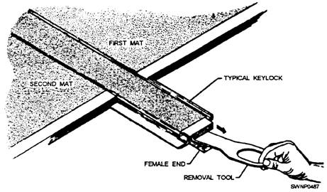
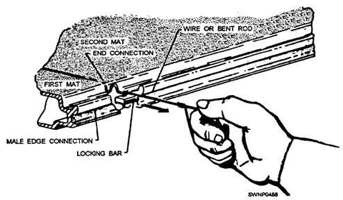
SECTION OF RUNWAY REPLACEMENT A section of runway replacement maybe required when groups of mats are damaged beyond repair or when excessive mat deflection and roughness, due to cavities under the mats, must be corrected. The procedure for replacing a section of runway is essentially the same with or without a guide rail installation. However, with a guide rail installed, removal of typical keylock sections will proceed from the outer edge of the runway regardless of which side of the guide rail the repair is to take place. Without a guide rail and when starter keylocks are used, typical keylocks must be removed from the right-hand edge of the runway (or taxi way) when facing the end of the runway from the transverse center line. This edge of the runway exposes the female end of the keylock into which the special removal tool must be inserted. The replacement of a section of the runway is accomplished in the following manner: 1. Remove the first typical keylock action by loosening the socket head screw at the first inboard connection. This screw only needs to be loosened until it is free of the male end of the adjoining keylock (about 7/16 inch). The screw should not be removed further since it is designed to be self-retaining and reassembly can be affected from this position. 2. Insert the prong of the removal tool under the turned down lip of the female connector and slide the keylock from its position, as shown in figure 11-35. NOTE: The initial 3-foot or 6-foot keylock section will have to be pried out since the exposed end is merely an unfinished cross-sectional cut and will not accept the removal tool. 3. Loosen the next and subsequent connectors, as described previously, and remove the remaining keylock sections. If mat distortion is minimal, you may be able to remove more than one keylock section at a time. 4. Use blocking and pry bars to lift the first row of mats high enough to allow the locking bars to clear. Each mat has one pry bar. All pry bars should be operated at the same time for the full width of the runway (or taxi way) to prevent warping of the mats. The mats will readily hinge at the first longitudinal mat joint. NOTE: If a guide rail has been installed, the adjacent mat maybe cut parallel to the guide rail. `This cut must be made so it severs the locking bar to allow the locking bar and the end connector to be removed from the guide rail. 5. With the row of mats raised, insert a bent rod or wire in the locking bar hole and remove each locking bar including the bars securing the cut piece of the guide rail. The first row of matting may then be disassembled and removed. (See fig. 11-36.)
Figure 11-35.-Typical keylock removal tool.
Figure 11-36.-Removal of locking bar. 6. With the clearance now provided, removal of the remainder of the matting and additional guide rail, as necessary to affect the repair, may be readily accomplished Remove the cut piece of guide rail aft of the repair area by removing locking bars and disconnecting the guide rail pins, using a pin remover, NAEC Part No. 414223-1. Slide the guide rail out of the mats. 7. Repair the ground surface, as necessary, before installing the guide rail and new or refurbished matting. 8. The installation procedure must be the same as that for the original installation. Replace the locking bars. 9. Reinstall matting over the repair area until the last row of matting is in place. At this point, this row of matting must be raised in unison with pry bars to permit installation of locking bars. NOTE: It will not be possible to insert locking bars between the guide rail and adjacent mats for this row. Therefore, a replacement mat should be installed next to the guide rail. A locking bar is built into the replacement mat. 10. Insert the typical keylocks in the reverse order in which they were taken out. Always use wood blocking between the hammer and connector if force is necessary to drive the sections into place. Excessive mat deflection and roughness, which can be attributed to cavities under the mats, can be repaired in the following manner: 1. Remove all mats that show excessive wear and deformation according to the instructions given earlier. 2. Fill all cavities under the mats and cover cavity areas with old matting. Areas should be reinforced with any available matting: M9M1, M9M2, AM-1, or damaged AM-2 mats. The mats in the bottom layer need not be joined together to save material and manpower. It is advisable to have the reinforcing mats touching, but it is not imperative that the mats in the bottom layer be interlocked. The mats in the bottom layer must be placed with the long dimension of the mats at right angles to the mats in the top layer. A double layer of matting should be considered in all cases where sandy areas can cause excessive mat roughness due to movement of the sand 3. Replace the top layer of matting according to the instructions given earlier. Before proceeding, note that a heavy-duty mat, as shown in figure 11-37, has been developed
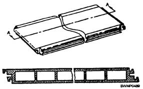
Figure 11-37.-Heavy-duty mat.
Figure 11-38.-Straightening of lower female edge.
Figure 11-39.-Straightening of upper female edge.
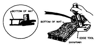
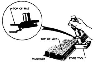
Figure 11-40.-Straightening of male edge. Heavy-duty mats are used under arresting cables to eliminate excessive dents and other external damage that occurs to regular matting during aircraft arrestment procedures. These mats are only used on the end of the runway where aircraft touch down. Heavy-duty mats are 6 feet in length and 18 inches wide after connectors are attached. They are painted Marine Corps green, color No. 23; the top surface is also coated with a nonskid material of the same color. Locking bars used to secure heavy-duty mats together are approximately 6 feet in length. |
|
Privacy Statement - Press Release - Copyright Information. - Contact Us - Support Integrated Publishing |