Custom Search
|
|
  |
|
|
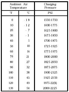
Functional Check This check will be performed at each acceptance/phased/SDLM inspection. It will also be performed after any adjustment procedures. Refer to Troubleshooting Chart (table 7-2) prior to making any adjustments. Materials required to perform the functional check include test stand 59A120 (test stand 59A120 is covered in detail in chapter 11 of this manual), scale (0 to 50 pounds), leak detection compound, and a toggle reset tool. Inspect leak detection compound before using it. Compound that is not clear and free from suspended material or sediment is considered contaminated and must be disposed of. Compound exhibiting peculiar odors such as acetone or alcohol is considered contaminated and must be disposed of. Emergency oxygen cylinder pressures used in this functional test are taken under ideal shop conditions of 70F or 21C. Variances in air temperatures directly affect charging pressures. Refer to table 7-3 for details. Ensure that the emergency oxygen cylinder is filled to 1,800 to 2,000 psi corrected pressure. 1. Connect the oxygen outlet hose of the kit to the bell jar coupling C-1 on the test stand, and ensure that valve V-2 is open and all other test stand valves are closed. 2. Attach the pull scale to the manual emergency oxygen release handle, and test for disengagement force. Ensure the manual oxygen release is of the separating type before attempting to disengage it. 3. Measure the force required to disengage the manual oxygen release. This should be 10 to 30 pounds, and the emergency oxygen system should actuate and indicate 45 to 80 psi on gauge PG-1 on the test stand. 4. Reinstall the manual oxygen release (if separating type) and reset the reducer. 5. Turn the oxygen supply cylinder to the test stand on. 6. Slowly open valve V-6 on the test stand and adjust the pressure on gauge PG-1 to 90 psi.
Table 7-3.-Amb~nt Air Temperature vs Charging Pressures 7. Measure the force required to disengage the manual oxygen release with a scale. This force should be 10 to 30 pounds. 8. Using leak test compound, check all pressure lines and fittings on the kit for leakage. No leakage is allowed. 9. Reinstall the manual oxygen release (if separating type) and reset the reducer. 10. Using valve V-6, increase pressure until the relief valve unseats. However, do not increase the pressure above 150 psi. Unseating can be determined by listening, and by observing gauge PG-1 on test stand. 11. Repeat step 10 several times to establish a correct pressure. Relief valve will unseat at 120 to 140 psi when pressure is increased, and reset at 110 psi minimum when pressure is decreased. The pressure is reduced below the opening pressure of the relief valve by closing valve V-6 and opening bleed valve V-5. Once reset, the relief valve will be leaktight. 12. Check the relief valve with leak test solution. No leakage is allowed. 13. Close valve V-6 and bleed oxygen pressure from the system by opening valve V-5. All pressure is bled when gauges PG-1 and PG-4 indicate zero pressure. 14. Close valve V-5. 15. Ensure that bleed valve V-2 is opened and all other test stand valves are closed. 16. Measure the force required to disengage the automatic oxygen release with a scale. This force should be 10 to 30 pounds when it disengages; the emergency oxygen system should actuate and indicate 45 to 80 psi on gauge PG-1. 17. Reset the reducer. 18. Open valve V-5 to bleed pressure. 19. When pressure is bled, as indicated by no indication on gauges PG-1 and PG-4, close valve V-5. Now, observe gauge PG-4 for 2 minutes. Any pressure rise indicates leakage in the valve seat of the reducer/manifold. 20. Open valve V-5 and close valve V-2. 21. Disconnect the oxygen hose from fitting C-1. 22. Ensure all valves on the test stand are secured. 23. Connect the oxygen outlet hose to fitting NIP-6. Ensure that valve V-10 is open and all other test stand valves are closed. 24. Connect the test stand hose between fitting NIP-5 and fitting NIP-4. 25. Move valve V-1 to the NIP-4 position. 26. Ensure that 1,800 to 2,000 psi is in the oxygen cylinder of the kit. 27. Pull the manual oxygen release. Slowly open valve V-9 to indicate 90 liters per minute on gauge PG-2. Oxygen pressure should be indicated as 45 to 80 psi on gauge PG-1. 28. Observe emergency oxygen cylinder pressure gauge and allow the system to decrease to 250 psi while maintaining 90 LPM and 45 to 80 psi pressure. When needle of this cylinder pressure gauge is between the E and F of REFILL, pressure is approximately 250 psi. 29. Close valve V-9. 30. With zero flow indicated on gauge PG-2, gauge PG-1 should indicate 45 to 80 psi. 31. Reinstall the manual oxygen release (if separating type) and reset the reducer. 32. Bleed the oxygen pressure from the system by opening valves V-5 and V-2. All pressure is bled when gauges PG-1 and PG-4 indicate zero pressure. 33. Disconnect the kit from the test stand. 34. Secure the test stand. 35. Thoroughly clean all areas wetted with leak test solution with clean water. Dry them with a lint-free cloth, filtered low-pressure compressed air, or by low-pressure nitrogen. 36. Recharge the emergency oxygen cylinder to 1,800 to 2,000 psi. 37. Perform a release handle pull test on the fully packed kit. (Refer to NAVAIR 13-1-6.3 for instructions.) |
 
|