Custom Search
|
|
 
|
||
|
The upperpart of figure 5-40 shows a two-view normal
multi-view projection of a block. Though
the line AB is parallel to the horizontal plane
of projection, it is oblique to both the vertical
and the profile planes. It is therefore not
a normal, but an oblique, line in the multi-view projection,
and it will be a non-isometric line
in an isometric projection or drawing of the same
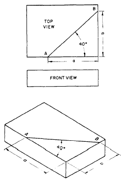
object. The line AB appears in its true length in the top multi-view view because it is parallel to the plane of the view (the horizontal plane); but it will appear as a non-isometric line, and therefore not in its true length, in an isometric drawing, as shown in the bottom part of figure 5-40. It follows that you cannot transfer AB directly from the multi-view projection to the isometric drawing. You can, however, transfer directly all the normal lines in the multi-view projection, which will be isometric lines appearing in their true lengths in the isometric drawing. When you have done this, you will have constructed the entire isometric drawing, exclusive of line AB and of its counterpart on the bottom face of the block. The end points of AB and of its counterpart will be located, however, and it will only be necessary to connect them by straight lines. Angles in Isometric.In a normal multi-view view of an object, an angle will appear in its true size. In an isometric projection or drawing, an angle never appears in its true size, Even an angle formed by normal lines, such as each of the 90-degree corner angles of the block shown in the bottom part of figure 5-41, appears distorted in isometric. The same principle used in transferring a non-isometric line is used to transfer an angle in isometric. The upperpart of figure 5-41 shows a two-view multi-view projection of a block. On the top face of the block, the line AB makes a 40-degree angle with the front edge. The line AB is an oblique (that is, not normal) line, which will appear as a non-isometric line in the isometric drawing. You locate the end points of AB on the isometric drawing by
Figure 5-41.-Drawing an angle in isometric. measuring distances along normal lines on the multi-view projection and laying them off along the corresponding isometric lines on the isometric drawing. The angle that measures 40 degrees on the top multi-view view measures only about 32 degrees on the isometric drawing. Note, however, that it is labeled 40 degrees on the isometric drawing. This is because it actually is a 40-degree angle as it would look on a surface plane at the isometric angle of inclination. Circles in Isometric. A circle in a normal multi-view view will appear as an ellipse in an isometric drawing. This is shown in figure 5-42, view A. A procedure that maybe used to construct an isometric circle is shown in figure 5-42, view B. The steps of that procedure are as follows: 1. Draw the isometric center lines of the circle. Then, using those center lines, lay off an isometric square with sides equal to the diameter of the circle. 2. From the near corners of the box, draw bisectors to the opposite intersections of the center lines and the box. The bisectors will intersect at four points (A, A, B, B), which will be the centers of four circular arcs. 3. Draw two large arcs with radius R, using Points A and A as centers, Draw the two smaller arcs with radius r, using Points B and B as centers. If the above discussion seems familiar, it should. It is simply an approximation of the four-point method you studied in the previous chapter. However, it can be used only when drawing isometric circles on an isometric drawing. |
 
|
|
|
||
|
|
Integrated Publishing, Inc. - A (SDVOSB) Service Disabled Veteran Owned Small Business
|